Post by Tom Clement
![]()
Beautiful PCB design has thrived in the past few years. With personal projects and event badges alike, hackers have been pushing the limits of the artistic beauty they can put in their circuit boards.
The community of PCB enthusiasts has experimented with combining colours of silkscreen, copper or ENIG, and solder mask to make sweet graphics. They’ve convinced PCB houses to use multiple layers of silkscreen, have stamped colours of their own, and have even gone multidimensional.
I got hooked on event badges after falling in love with SHA2017, and have been involved in making badges for a bunch of events ever since. For every new badge we make, we have some innate drive to push the boundary a bit further to what was already done before, both in hardware and what experience it gives its users, and in the aesthetics of the badge.
So naturally, when people asked for the re-production of the ESP32 WiFi LED panel badge a bunch of us had made for CampZone 2019 that had inkjet printed dithered single-colour graphics, I started thinking about what’s next. Stumbling upon a hacker news post that showed full-colour UV inkjet printed PCBs by an Australian company called Little Bird, I was amazed. Even though the limitations of PCB design had previously resulted in super creative art, having full-colour graphics in your toolbox could open up so many more possibilities.
The comments section of the hacker news article showed that apparently UV printing had already been done on PCBs over a decade ago, but I hadn’t seen anyone in the badge scene use it before. So I got cracking with our (amazing!) production partner Norbert of ALLNET China, and together we started experimenting with printing on our PCBs. Boy, were we in for a ride! In the remainder of this post, I’ll try to summarise all of the things we learned along the way.
First attempts
We first started thinking about getting to full colour prints by using the same dithering technique we had used for CampZone 2019, but now with many colours, because I had no idea how normal UV printing worked. Luckily, my friend Hans (aka “the maker maker”, whom I got to know via Ian of Dangerous Prototypes) mentioned that industrial UV printers can print on many materials out of the box, including PCBs.
Indeed, after getting some weird looks from a company that normally makes physical store signs with their UV printers, they were happy to put some of our old unpopulated CampZone 2019 PCBs in their printer and turn them into retrowave heaven:
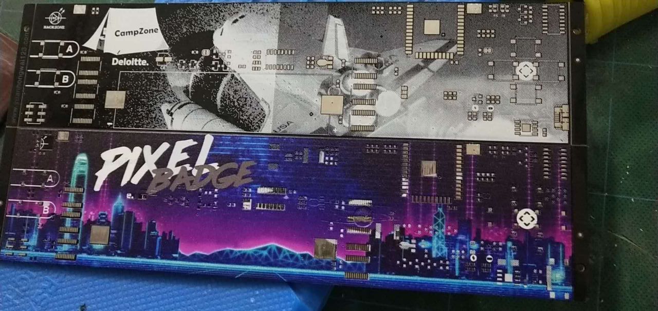
This initial print used standard CMYK UV ink, plus a separate white UV ink for the whites.
The result looked great, but we hit the same problem others before us had hit: putting printed PCBs in a reflow oven messes with the colours a lot. You might remark that it makes more sense to print on the PCBs after they have been pick&placed and soldered. However, the print accuracy of inkjet printers is a function of the distance between the print jet and the object. Our printer could only move 3mm above the PCB (which was not enough for our components), and even if it could move higher the print quality would be quite bad. So instead we worked on getting the UV ink handle reflowing better.
Lesson 1: making white stay white
After reflowing, the boards looked like this:
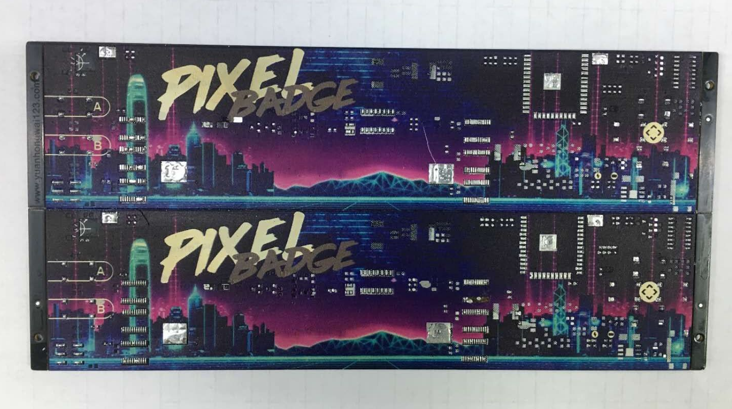
You’ll notice that all colours become a bit more dim. Red seems to lose more of its edge than green and blue. Most importantly though, the white ink is turned into a nasty aged yellow. Most of the colour changes we could live with, so we didn’t correct for them in our designs (you’ll see later that our final art worked nicely with the reflow process). In general one can try to correct for the changes in their source design, of course.
The whites were totally unacceptable though. It made the badge look old and yucky. We considered diving into the world of different UV inks, and finding a white ink that was more heat tolerant. Then we had a simple realisation: the perfect heat resistant white ink we all know already was simply white soldermask or silkscreen. Because we want to keep the front of the badge black to keep nice contrast, we opted for keeping the mask black and experimented with white silkscreen on the back.
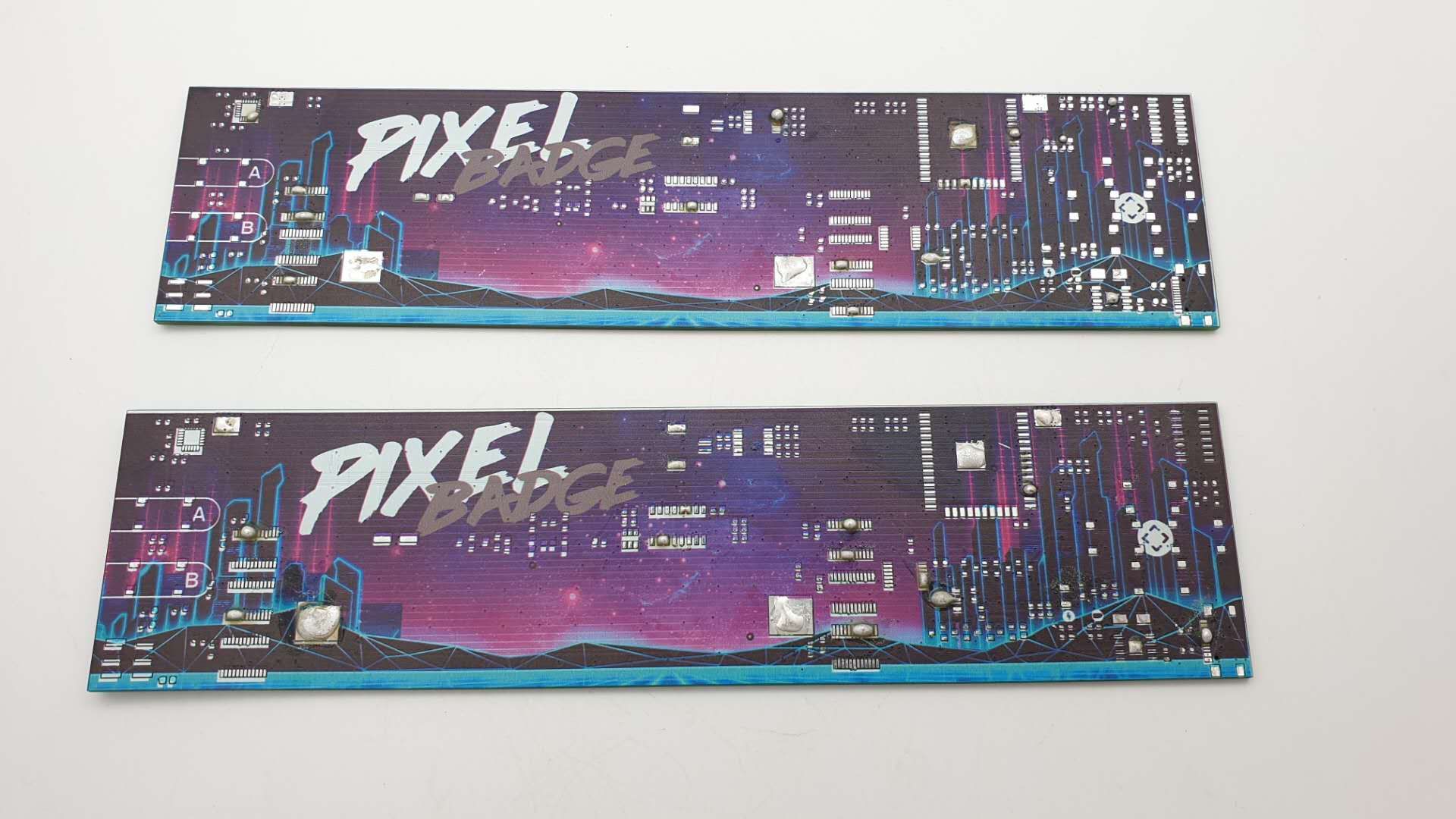
So we modified our art such that the white parts were cut out of the design, which meant no ink would be placed there, and made PCBs that were completely covered with white silk outside of the component pads. The result was awesome, even after reflowing:
Lesson 2: getting decent alignment
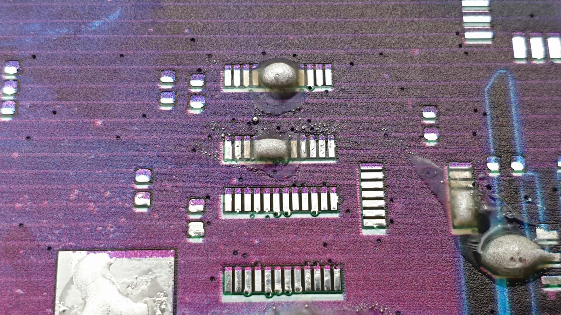
At this point we had PCBs that looked nice, but were in no way usable to solder on: many pads were partially printed over.
We were printing entire panels at a time, and observed that even when we got perfect alignment on one panel, the next would be wildly out of spec again.
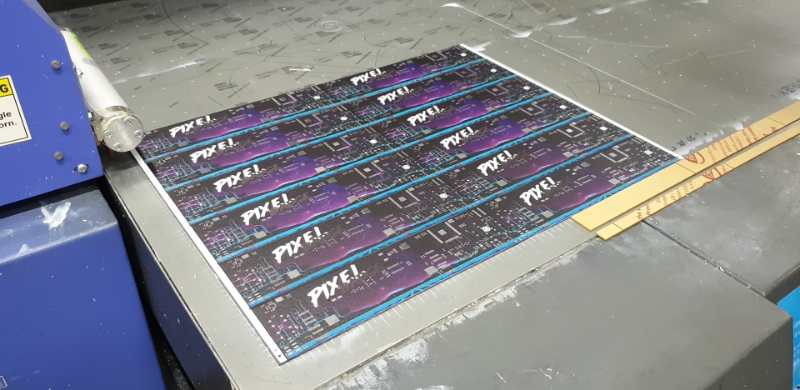
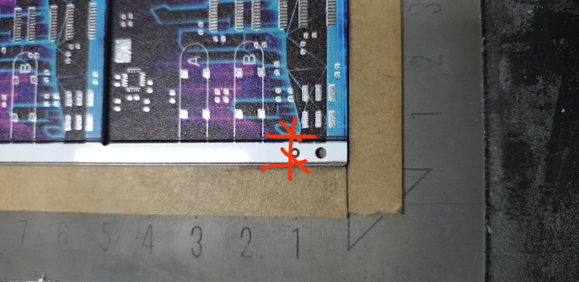
It turned out that even though the contents of a panel are extremely dimensionally accurate, the edge rails width was not. PCB houses use alignment holes and markers on the edge rails to align their processes, and don’t need to care if there was ~0.2mm extra width on the rails after such a mark or not.
Aside from this, it is in general hard to get sub-mm accuracy on big industrial UV inkjet printers. For future projects, we will at least try to get better repeatability between panels by making a (very thin) jig that is a bit wider and taller than a panel, that has pins on which we slide the alignment holes of the panel. This allows you to fasten the jig to the printbed, and assure that once you have tediously aligned the jig the future panels will print reasonably well.
Lesson 3: more pin margin == more better
The alignment issue of the previous section was enlarged because we were stubborn. We felt that having close to no whitespace around pads (0.1mm) would look so much better, so literally any misalignment would immediately cause pads to be partially overprinted. It does look incredible in our opinion, but was the cause for a lot of blood, sweat, and tears. We struggled to get our failure rates below 50% (which is ridiculously high; normally we would want <1%).
This makes the Founder’s Edition extra special, as it is highly likely our last project that will have this insanely tight printing margin!
![]()
For future projects, we will probably use a ~1mm margin around pins to make our life easier. For making this margin less apparent, we’ll likely incorporate the underlying mask or silk colour in the design. That way you’re not looking at chunks of white across the board :)
So what now?
By sharing what we did, we hope to make you all excited about getting full-colour art on your designs. We’d be super psyched especially to see the #badgelife community pick up this neat trick for other event badges.
And, if you’re still looking for something to do this Christmas and like WiFi-enabled LEDs you can program in Python: you can still get one of our Pixel Badges here. Happy holidays!
Do you want to know more, or would you like our help bringing UV inkjet printing into your project? Feel free to reach out on our Discord or via info@curious.supplies.